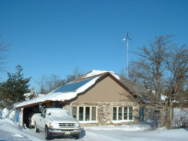
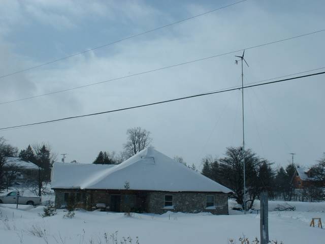
2000 - Designed and built an energy efficient and self-sufficient home on the Bruce Peninsula using wind power and solar thermal energy.
2002 - Founded TRUE-NORTH Power Systems and the FREE Wind Test Center designed a full line of renewable technology including small wind turbines, solar mounting and tracking systems and tilt towers. With American investor Norm Guice we established True North Power NG Inc and developed an entire line of small wind turbines WIND ARROW and solar mounting and tracking systems including Chanellox rail system, PowerSeries mounts and Sunpoint2GPS solar trackers, based in Ayr Ontario. These solar products are now manufactured and sold in Ontario and Turkey under license.
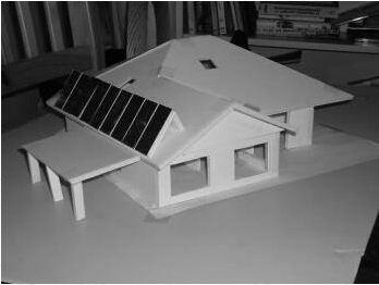
This 2800sf custom designed near-ZERO emissions home was built in 4 months near Lions Head ON, Bruce Peninsula and made use of passive and active thermal solar heating with a small wind turbine for self sufficient energy using AGM sealed batteries for off-grid operations. With lots of pre-planning construction started March 2001 and was we were able to move in 7 July to complete interior finishing 4 weeks later. A 1000gal stainless storage tank is headed by a solar thermal heat exchanger with 18kW of solar thermal panels on the roof.
True-North Power Technical Bulletins
EMAIL CONTACT: Primary email contact for truenorthpower.com has changed. Please use the email below Call or email for information on operations, technical support, troubleshooting or design licensing
The documents below contain the most up-to-date information and techniques to make it easier to install and maintain your system.
Some of this information that may not be contained in downloadable manuals
Not all bulletins apply to all models, so please note which systems each applies to
Small details in the installation and operators manuals are important — Oversights can lead to serious damage or injury
Some alternative installation techniques or additional/optional components can make maintenance and support much simpler and easier
15 JULY 2020 - Sunpoint2GPS UPDATE NOW AVAILABLE! Tech Bulletin 9.1: The Solution We are aware that many but not all Sunpoint2GPS trackers are experiencing "Failure to TRACK" problems for some unknown reason. We have been wrestling with this issue for over a year now and during the last few months we have been collaborating with Gravity Sun Power of Creemore who has developed his own modification to the controller that resolves the problem by modifying the green board and replacing the software with new code that adds new maintenance functions as well. Any systems still using the original BLUE BOARD (Motor Controller) is encouraged to replace it as well with the "Anaheim Board" which is reliability improvement as well. Jeff can help you with that too.
I have not been directly involved in this upgrade solution but Jeff WIlliams of www.gravitysunpoeer.com is personally modifying controller boxes now. Please contact him directly for pricing and availability at Gravity Sun Power. Gravity Sun Power. Creemore, ON L0M 1G0. Phone. 705.466.5741. Fax 705.466.6020. email . . .jeff@gravitysunpower.com.
MAY 2019 - CRITICAL UPDATE - All Sunpoint2GPS Trackers Tech Bulletin 9: GPS CHIP ROLLOVER
We are aware of a GPS issue effecting many, if not all, SKM53 GPS receivers made prior to year 2019. The Sunpoint2GPS tracker uses this SKM53 receiver, that was updated last in the year 2000. If your Sunpoint2GPS tracker is facing roughly east most of the day, going south overnight and then repeating, you likely have this 8bit SKM53 chip. Our SunpointsGPS v7.0 software does not appear to be effected and should not need an upgrade, but the system wide 10bit timer rollover that happened in April 2019 leads to improper calculation of the solar ephemeris. It is possible that your system appears unaffected at present, but the error will manifest itself when the system is RESET any time after 6 APR 2019.
The satellite date (week), is handled through an 10 bit number that rolls OVER every 2 to the 10th weeks (1024 weeks or 19.6 years) . . This is the first time this GPS hardware limitation has effected True North Trackers and it occurred after the most recent roll over at midnight 6/7 April 2019. Many of you might remember Y2K problems with computers as the date/time change effected many digital clocks and computers. This appears to be a similar event. Any system using this GPS receiver will require a new version of the SKM53 GPS chip. SKM53 receivers are now using a 13 bit (or higher) week rollover that should not require an update for at least 157 years , or until June 2176. That should solve the timing problem . . at least for anyone currently on this planet. As of 1 Jun 19 we have still not confirmed the problem solution is resolved completely and testing continues.
We now have new 10bit chips GPS chips for testing and work continues to confirm our own software is sufficient and will not require modification. Replacement GPS chips should be available sometime in June 2019 at a cost of $100CDN each + taxes ($113.50). Installation is extra but can be done by anyone with a bit of specialized knowledge on the system. For installation contact Jeff Williams of Gravity Sunpower, <[email protected]> Gravity Sunpower CONTACT. The procedure will also be published in this Bulletin if you want to do this yourself, as soon as we confirm the fix. Consult Jeff or your local solar installer or maintenance tech for installation costs. Shipping the part will be a flat $10 for any number of chips shipped anywhere in Canada, email [email protected] or call (416) 523-5230 for details.
Tech Bulletin 10 - Motor Controller - Blue Board "Anaheim Upgrade"
The original "Blue Board", is used to control the motor function and is a highly sophisticated controller with many advanced functions available that we had planned to use for future Sunpoint features. It used a separate 24pin DIP True-North programmed software (v5.42) but was eventually, retired in favour of a simpler more industry standard motor controller that simply did START STOP LEFT RIGHT and had some reasonable fault tolerance. The other features were just too many "bells and whistles" and this left it more prone to failure.
The Anaheim Upgrade is recommended if there is ever a fault traced to the blue board. This upgrade is available by sending the complete controller with wires and switches still attached (EVERYTHING INCLUDING WIRES AND SWITCHES - UP TO BUT NOT INCLUDING THE MOTOR).
Call David at (416) 523-5230 for pricing and availability and also check out Bulletins 5, 6 and 7 if you have an older original unit.
PRE 2012 TECHNICAL BULLETINS
PowerSeries Mounts
Tech Bulletin 1:General Maintenance --PLEASE READ page 2 of the warranty card Any PV mounting systems should be checked occasionally for loose bolts or electrical connections. Even non-tracking systems require regular inspections so that small problems like a loose bolt or wire do not lead to major failures or damaged components. Annual inspection and greasing of the slew drive is mandatory, but monthly observation and checking for connections and physical security is highly recommended.
Check alignment accuracy in the morning, shortly after sunrise. Check the array angle right AFTER it has moved. If ahead of the sun, move the North Probe to the RIGHT and equal number of degrees. IF lagging or behind the sun, move the North Probe to the LEFT. With multiple towers, once they are aligned together they will all move and track in synch with each other since they are all working off the same satellite signal. The first time or after any restart they may be off by a few degrees due to the different START times. However, on the next morning they will re-synch at sunrise.
Tech Bulletin 5:TILT Actuator Separation WARNING POTENTIAL PANEL DAMAGE (11 November, 2011) All SP5000 and SP3600 owners are being warned about the potential separation of the base of the tilt actuator. There has been one incident where the actuator arm separated from the base due to a design flaw in the actuator whereby the actuator CASE is the weakest component that can break in the unit. Should the actuator base separate the array can tilt fully vertical and the panels may be damaged by striking the concrete base. Both TRUE-NORTH Power and manufacturer are investigating. We strongly recommend securing the array from exceeding maximum tilt by adding a safety strap or cable between the two actuator end points. Owners can receive a free safety clamp and installation instructions by contacting Cooke & Associates Inc at ([email protected]) or (416) 523-5230.
SunpointGPS Tracker
Tech Bulletin 5: Solar PV Relay and Software compatibility (12 October 2011) Current Sunpoint2GPS software versions are:
ASTRO BOARD - Firmware Version 6.0.4R (R stands for "reverse solar relay") Current Version 7.0 has done away with these issues. In September 2011, we reversed the function of the Solar Charging Relay in order to save energy since the relay was set as Normally Open (NO) and continuously using power to charge. The reversal changed to normal status to Normally Closed (NC), which uses no energy unless the battery is full, and it then disconnects the charging circuit. This then only happens when there is an excess of energy. The "4" designates - Automatic fault recovery for motor board failure to report "Move DONE". Whenever the motor board is given a step command that does not complete within 60 seconds, the controller will turn the MOTOR board OFF and ON and reissue the command. If you see this action happening every few seconds and NOT recovering, simply RESET the controller by powering OFF for a few seconds.Be sure to unplug the solar INPUT first and plug it back in LAST.
MOTOR BOARD - Firmware Version 5.3 ( This board is now obsolete and has been replace with a simpler more effective motor controller that does note require any programming). It uses only START STOP and REVERSE motor commands. The v5.3 update modifies the start and running sequence to eliminate stall possibilities under a wider range of speed. Earlier versions may be prone to a random stall during the motor START command and this would not report the error. In not reporting, the motor board would simply stay ON and continue to drain the battery without automatic recovery.
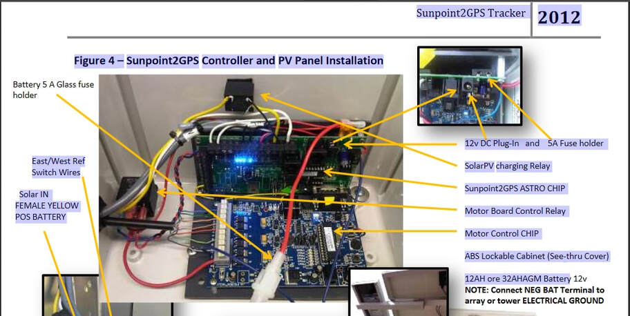
Tech Bulletin 6: Controller Grounding Note The SunpointGPS install manual does not include the grounding note that the NEG BATTERY terminal should be connected to the rear mounting screws for grounding purposes. . . as shown below. Tests show that nearby lighting strikes or other electrical disturbances can effect the controller function causing the tracker to halt operations requiring a manual restart. NEG terminal grounding is this way may prevent such occurrences.
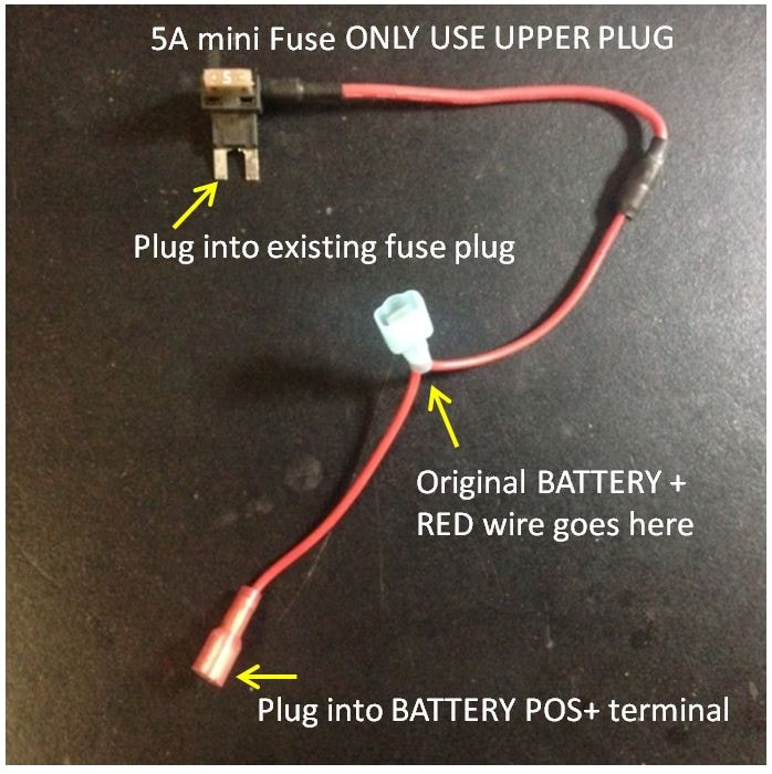
Tech Bulletin 7: 120AC Plug IN - REDUNDANCY FUSE WIRE. An OPTIONAL 120v AC power supply can be plugged into the Sunpoint2GPS controller at the top right of the board with a 5A (Auto mini-type) fuse located just above it. (see your manual pg12 below). This power configuration is in parallel to the battery power sources but under certain conditions may still allow the 12v battery to bypass either one of the redundant Fail Safe KILL switches located below the EAST and WEST reference switches. Contact True North Power if you think your units may have this vulnerability and wish to retrofit the AC power plug wiring. KILL Switches only activate to cut all power from the battery in case of a runaway motor controller. With AC plugged under certain conditions this may still allow power to the controller. It is recommended that ALL Sunpoint2GPS POWER SOURCE WIRING SHOULD BE CHECKED and MODIFIED TO INCLUDE A BYPASS FUSE THAT OVERRIDES BOTH THE BATTERY POWER FUSE AND THE AC ADAPTER. SIMPLY UNPLUG THE BATTERY AND PLUG IN THIS EXTRA CONNECTION BETWEEN THE BATTERY, THE EXISTING FUSE AND THE AC PLUG-IN. The diagrams below show the wiring required. When installed there will then be two fuses in series that can redundantly inhibit power from all sources.
Tech Bulletin 8: Solar Charging Solar charging is normally ON and is only turned OFF when the program energizes the small black Solar RELAY. The YELLOW solar lead is POSITIVE and to confirm the system is charging: Measure the voltage on the leads coming FROM the PV panel. YELLOW male from the PV panel should be positive and in good sun should be 15-20v. While the PV is NOT plugged in measure the continuity between the incoming and outgoing YELLOW terminals of the little black RELAY inside the controller case. They should be connected internally causing a BEEP. Note that YELLOW from the RELAY output should be wired to BMAIN on the green controller board and the smaller TRIGGER wire from the RELAY should be in the terminal on the right of BMAIN labeled RC0-0. See page 13 or 14 photos of the Sunpoint manual. With this confirmed, when the solar PV is plugged in then either YELLOW terminal on the RELAY should measure BATTERY voltage and in good sun you should notice it rising slightly over what was measured when the small PV panel was NOT plugged in. This confirms the PV panel is both connected properly and charging normally.